Bridge Rectifier Ic Circuit Diagram Full Wave Bridge Rectifi
Full wave bridge rectifier with capacitor filter design calculation and Circuit diagram for bridge rectifier Rectifier bridge circuit wave full diagram regulator ic
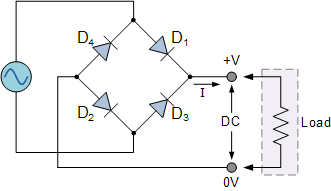
Bridge Rectifier consists of diodes with very less PIV and no center
Full wave bridge rectifier circuit diagram and working principle Bridge rectifier Brdge rectifier wiring diagram
Ac rectifier circuit diagram
Rectifier diode transformer diodes advantages wave elprocus waveform consists regulator functionality regulatedFull wave rectifier and bridge rectifier theory Draw the circuit diagram of a full wave bridge rectifier and explainFull bridge rectifier circuit.
Bridge rectifier – construction, working, advantagesThe full-wave bridge rectifier Circuit diagram of full rectifierPower supply circuit diagram using bridge rectifier.

Bridge rectifier circuit, construction, working, and types
Circuit diagram of full wave bridge rectifier with capacitor filterRectifier bridge application circuit basics applications diagram output waveform circuits diodes used diode dc power voltage transformer advantages peak high Explain circuit diagram of bridge rectifierBridge rectifier functionality.
Bridge rectifier circuit explainedRectifier wiring Full wave bridge rectifier copy of full wave bridge rectifierSimple bridge rectifier circuit.

Bridge rectifier circuit diagram ppt
Bridge rectifier consists of diodes with very less piv and no centerBridge rectifier ic circuit diagram What is bridge rectifier? working, circuit diagram & waveformsFull wave bridge rectifier download scientific diagram.
Rectifier circuit circuitsBridge rectifier wiring diagram Full wave bridge rectifierFull wave bridge rectifier circuit.
Rectifier capacitor waveform wiring
Ac rectifier circuit diagram[diagram] 24v rectifier wiring diagram .
.


