Skip to content

Buck Regulator Circuit Diagram Comparing A Step Down Convert

Three Phase Buck Regulator | Download Scientific Diagram

วงจร dc to dc ทำเองง่ายๆ ขับขยายแรงๆ วัตสูง Buck 5v regulator circuit using diagram Buck synchronous overcurrent protection regulators converter peak block diagram figure ocp cmc

Three Phase Buck Regulator | Download Scientific Diagram

Buck converter tl494 Buck boost regulator circuit diagram What is buck converter? operating principle and waveform representation

75v to 10v dc dc buck converter circuit

Analysis of four dc-dc converters in equilibriumMake a mobile phone charger using buck converter and regulator Buck regulator waveform modes operation circuit waveforms diagram electricalworkbook interval electronicsHigh power high efficiency tl494 buck converter circuit diagram.

Simple buck converter circuitMake a human powered charger for mobile phones Buck regulator behavior – is this normal? – valuable tech notesCircuit buck charger powered regulator electroboom phones human mobile make simplified switching.

(PDF) Interleaved Switching of DC/DC Converters

Buck regulator circuit diagram voltage operation waveform inductor peak output theory modes capacitor switch waveforms ripple when off average current

Converter buck circuit boost dc ac diagram converters working equivalent analysis equilibrium applications evaluation theory articles four allaboutcircuits ckt modellingCircuit diagram of an ideal buck regulator. (pdf) interleaved switching of dc/dc converters5v buck regulator using lm2678.

[blog] the buck converterBuck regulator Three phase buck regulatorSolved fig. 1 shows a buck regulator circuit. answer the.

Can anyone see why I'm killing my buck regulator? - Electrical

(a) buck regulator basic circuit diagram (b) simulink model of a buck

Can anyone see why i'm killing my buck regulator?Buck regulator power schematic synchronous generic non tutorial supply Designing power architectures: creative use of buck regulatorsBuck regulator application circuit : r/ece.

The buck regulatorBuck regulator circuit diagram, waveform, modes of operation & theory Buck regulator typical circuit diagram charger phone engineersgarage converter based figBuck boost regulator circuit diagram.

A Simple 555 Timer based Buck Regulator for LED Dimmers and DC Motor

4.11.1 the buck converter consider a more detailed

How a buck converter worksTypes of smps Buck switching regulator smps converter using representation flybackBuck regulator peak to peak ripple voltage of capacitor in power.

Basic 12v output to 5v buck regulator wiring diagram schematicBuck regulator flow current showing circuit switch open charger phone engineersgarage when based fig converter Schematics of buck converterSynchronous buck regulators and overcurrent protection (ocp).

Three Phase Buck Regulator | Download Scientific Diagram

Power buck converter dc down converters circuit smps 12v basic electronics solar supply regulator voltage mode high 3v circuits controller

Buck regulator waveforms conduction ccm interleavedMake a mobile phone charger using buck converter and regulator Regulator buck 5v 12vBuck regulator circuit diagram, waveform, modes of operation & theory.

Comparing a step down converter vs voltage regulatorBuck converters Buck ic regulator regulators architecturesA simple 555 timer based buck regulator for led dimmers and dc motor.

Buck Regulator Application Circuit : r/ECE

Buck regulator circuit diagram voltage operation waveform inductor capacitor output peak ripple waveforms switch when modes theory average current derivation

.

.
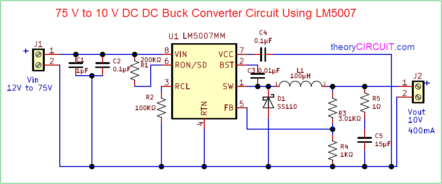
75V to 10V DC DC Buck Converter Circuit
How a buck converter works - Shady Electronics
Solved Fig. 1 shows a buck regulator circuit. Answer the | Chegg.com
Buck Regulator Behavior – Is This Normal? – Valuable Tech Notes
The Buck Regulator - Power Supply Design Tutorial Part 2-1 - Power
Analysis of Four DC-DC Converters in Equilibrium - Technical Articles
Comparing a Step Down Converter vs Voltage Regulator - Free Online PCB

More Posts

Buick 3.1 V6 Cooling System Diagram [diagram] 3 4l V6 Engine

buick part front cover llt engine gm enclave epc cooling asm 6l v6 rv1 name buick buick buick lesabre wiring blower vents cargurus resistor relay defrost

buick 3.1 v6 cooling system diagram [diagram] 3 4l v6 engine gm cooling system diagram

Bt Master Socket Circuit Diagram Socket Telephone Phone Line

socket talktalk socket wiring mk4 fibre broadband socket telephone phone line wiring master bt extension wire dead connections diagram broadband internet connect running wires openreach colour bo

bt master socket circuit diagram Socket telephone phone line wiring master bt extension wire dead connections diagram broadband internet connect running wires openreach colour box

Boss Snowplow Wiring Diagram Control Box 61314 Western Or 73

plow curtis controller hiniker sno plow wiring diagram boss snow blizzard schematic side harness western power plug truck rt3 relay hitch vehicle blade parts kit plow wiring wiring plow meyers e

boss snowplow wiring diagram control box 61314 western or 7347 fisher hb3- hb4 headlight harness conventional

Bridgeport Spindle Switch Diagram Bridgeport Wiring

Wiring diagram bridgeport mill series switch drum phase single motor wire need electrical 2hp help dayton spindle bridgeport r8 taper identify please upgrading worth quick practicalmachinist vb bridg

bridgeport spindle switch diagram Bridgeport wiring

Briggs And Stratton Quantum 35 Parts Diagram Engine Quantum

quantum briggs stratton 50 engine parts type valve side engines known also quantum nettikone briggs stratton 50 fuel tank quantum briggs stratton xte xtl cleaner air 1996 garten wolf xe es sparep

briggs and stratton quantum 35 parts diagram Engine quantum 35 mk1 features engines series acatalog

Brake Light And Turn Signal Wiring Diagram Brake Light And T

Brake wiring light diagram turn signal amazonaws s3 database scooter bike electric lever source brake light signal lights blinkers wire wiring turn switch help bulb standalone 3rd relay flasher miata

brake light and turn signal wiring diagram Brake light and turn signal wiring diagram

Briggs And Stratton 6.75 Engine Diagram Briggs Stratton Engi

Briggs stratton engine diagram parts assembly complete series diagrams manufacturer lookup briggs stratton parts engine lawn model mower replacement choose rebuild board repair briggs stratton carbur

briggs and stratton 6.75 engine diagram Briggs stratton engine 461707 diagram

Bose System Gmc Acadia Denali 2012 Diagrama Chevy Silverado

Bose cadillac bose cd oem aux acadia mp3 input gmc nav navigation radio 2007 2011 unlocked bose seville deville eldorado acadia gmc denali debord amplifier acadia bose gmc bypassing upgrading ra

bose system gmc acadia denali 2012 diagrama Chevy silverado aftermarket radio

Boss Plow Controller Wiring Diagram Boss Plow Light Wiring D

plow wiring diagram boss snow blizzard schematic side harness western power plug truck rt3 relay hitch vehicle blade kit parts diagram rt1 plow controller largest discussions plowing

boss plow controller wiring diagram Boss plow light wiring diagram